
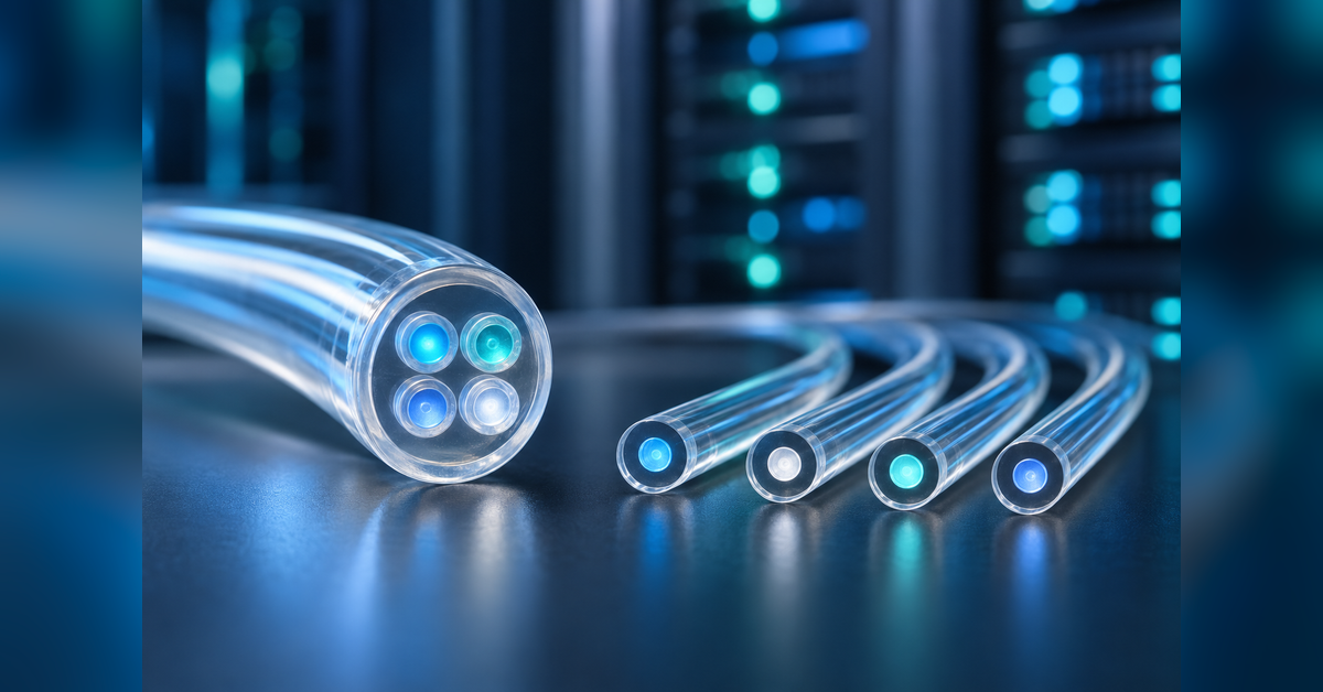

Multicore fiber can place several optical pathways inside one shared cladding, which makes it relevant when cable, tray, connector, or conduit space is under pressure. The buyer’s job is not to count cores. It is to determine how many cores can become accepted, usable, and supportable paths.
That distinction matters for AI data halls, campus connections, carriers, construction teams, and connectivity vendors. A credible plan must connect the glass to fan-outs, connectors, splices, tests, optics, operations, supply, and measurable economics.
OPTK NETWORKS CASE STUDY
Telecom expertise becomes more valuable when buyers can find and trust it
Cody Clegg and the OPTK Networks team discuss how Percepture helped present telecom expertise through search, AI, and market-authority programs. This case study establishes the working relationship; it is not evidence of optical performance.
What is Multicore fiber?
Multicore fiber is an optical fiber that places two or more light-guiding cores inside shared cladding. Each core can provide a spatial pathway, increasing pathway density without adding the same number of separate strands. Practical value depends on crosstalk, connectors, fan-outs, splicing, optics, interoperability, field operations, and economics.

“The primary advantage is capacity density. Conduit space is finite, especially in dense data center corridors.”
Cody Clegg
Director of Sales & Marketing, OPTK Networks
The executive summary
Density is the opportunity
The multicore architecture can increase the number of spatial paths associated with one physical strand.
The system sets the result
Core count does not establish end-to-end throughput. Interfaces, loss, crosstalk, optics, mapping, and operations still control usable performance.
Field readiness is separate
A laboratory link does not establish that construction and operations teams can install, test, repair, and support the design repeatedly.
Economics follow acceptance
Only paths that pass technical and operational limits should enter utilization, cost, revenue, or payback models.
The Percepture proof stack
Percepture’s role is technical-market authority: organizing expert knowledge into accurate search, GEO, content, public-relations, and buyer-education programs. Percepture does not engineer, splice, certify, or operate optical links.


Programs can combine generative engine optimization services, technical search architecture, expert-led technical content, and emerging-technology PR.
Who should use this guide?
Network and AI leaders
Use it to separate spatial pathway density from verified workload capacity.
Facilities and construction teams
Use it to evaluate how a multicore architecture affects tray, conduit, closure, labor, tool, training, and repair requirements.
Finance and procurement
Use it to compare lifecycle cost, supply options, support, interoperability, and exit risk.
Technical marketers
Use it to build accurate claims, evidence ladders, and buyer education without turning nominal core count into a performance promise.
What is the difference between multicore, multi-fiber, multimode, and hollow-core designs?
Multicore fiber describes multiple physical cores within shared cladding. A multi-fiber cable contains multiple separate strands. Multimode describes propagation modes within a core. Hollow-core designs address propagation through an air-filled structure rather than adding multiple solid-glass cores for spatial density.
| Term | What it describes | Buyer boundary |
|---|---|---|
| Multicore optical fiber | Two or more light-guiding cores in shared cladding | Evaluate every core and the supporting ecosystem |
| Multi-fiber cable | Multiple separate fiber strands inside a cable | Do not treat strand count as multicore architecture |
| Multimode fiber | Multiple propagation modes within a core | Do not use the terms interchangeably |
| Hollow-core fiber | A structure that guides light mainly through air | Compare it when propagation behavior or latency is the problem |
For the separate latency and propagation question, see Percepture’s guide to hollow-core fiber.
How does Multicore fiber work?
Each light-guiding core provides a spatial route through the shared cladding. In an uncoupled or weakly coupled design, engineers generally seek cores that behave mainly as separate paths. In a coupled-core design, interaction between cores becomes part of the system and may require signal processing.
What is space-division multiplexing?
Space-division multiplexing carries parallel channels through separate spatial paths. In this architecture, those paths can be different cores. SDM can be combined with wavelengths and modulation, but every spatial channel still needs a controlled path from transmitter to receiver.
Why do core pitch and crosstalk matter?
Core pitch is the center-to-center spacing between neighboring cores. Inter-core crosstalk is unwanted optical energy coupling between cores. Geometry, coupling model, wavelength, distance, bends, manufacturing tolerances, and complete link conditions must be evaluated together rather than reduced to a single generic limit.
| Core model | Behavior | System requirement | Main control |
|---|---|---|---|
| Uncoupled or weakly coupled | Cores act mainly as separate paths | Core access, mapping, and crosstalk control | Validate each core through the complete link |
| Coupled-core | Signals interact across cores | System-level processing | Test processing complexity and operational fit |
Does four-core fiber mean four times the capacity?
No. A four-core design can provide four potential spatial paths, but it does not guarantee four times the usable network capacity. Every path must be connected, mapped, tested, accepted, monitored, and matched to optics and workloads before it should be counted.
Pathway density and throughput answer different questions. Pathway density measures accepted optical paths within a physical footprint. Throughput measures verified data delivery under defined link and workload conditions. A buyer should keep those numbers in separate columns.
- Potential spatial paths: the nominal number of cores available by design.
- Accepted optical paths: cores that pass all technical and operational limits.
- Verified throughput: measured end-to-end output under the selected architecture.
- Useful capacity: accepted performance that supports a real workload or service.
Design teams planning data-center interconnect should model these layers alongside distance, redundancy, optics, and failure domains.
What are the benefits and risks of Multicore fiber?
The central benefit is potential pathway density. More spatial paths may fit within a strand, cable, tray, connector, or conduit plan. That can matter where adding physical routes is difficult, where cable handling affects schedules, or where long-range connection growth is substantial.
The risks sit around the fiber as much as inside it. Buyers must address alignment, insertion loss, polarity, core mapping, fan-in/fan-out devices, connectors, splicing, testing, monitoring, repair, training, supply, warranties, and interoperability. Conventional high-count or reduced-diameter cable may remain the lower-risk answer when space is not the binding constraint.
Density problem scorecard
A density-planning scorecard should connect each claimed density benefit to technical, operational, and financial evidence.
| Question | Evidence to collect | Decision signal |
|---|---|---|
| Are pathways genuinely constrained? | Tray, conduit, cable, connector, and closure baselines | A documented physical limit exists |
| Can a conventional option solve it? | Ribbon, high-count, reduced-diameter, route, and topology comparisons | The lower-risk option is insufficient |
| Can every core be accessed? | Connector, fan-out, splice, polarity, and core-map plan | Every interface has an owner and limit |
| Can operations support it? | Tools, training, repair, spares, and escalation procedures | The field model is repeatable |
| Can finance value accepted paths? | Lifecycle cost, utilization, avoided cost, and workload value | The model excludes unaccepted cores |
Run a readiness diagnostic before choosing a fiber architecture
Use a structured diagnostic to identify the density constraint, buyer committee, available proof, and commercial audience before building a technical market narrative.
The Percepture Multicore Density-to-Deployment Control System
This seven-stage methodology helps leaders decide whether Multicore fiber creates enough usable pathway density and business value to justify a new connectivity ecosystem. The rule is simple: an added core creates value only when it becomes a stable, accessible, testable, repairable, and economically useful path.
- Density truth: document paths, endpoints, growth, cable, conduit, trays, connectors, labor, and schedule.
- Architecture fit: compare conventional cable, ribbon, reduced-diameter cable, multicore designs, hollow-core options, topology changes, and civil expansion.
- Fiber evidence: define geometry, coupling, wavelengths, distance, loss, crosstalk, bends, temperature, and acceptance limits.
- Core access: map fan-outs, connectors, splices, orientation, polarity, optics, switching, and interfaces.
- Field readiness: test pulling, closures, tools, training, inspection, repair, spares, support, and warranties.
- Pilot: build a representative link, compare it with a control, test every core, and exercise fault and repair procedures.
- Scale and proof: standardize designs, contracts, supply, operations, monitoring, claims, and economic reporting.
Technical companies can connect this evidence system to public relations strategy, infrastructure buyer intelligence, and omnichannel market education.
Where could Multicore fiber create value first?
The strongest candidate environments are those with a documented density constraint and a manageable link ecosystem. Multicore fiber is most credible when that constraint can be tested against a conventional control. AI data halls, campus links, capacity-constrained terrestrial routes, subsea research, and sensing may present different opportunities, but they do not share one universal design or business case.
| Environment | Potential value | Proof required |
|---|---|---|
| AI data halls | More potential optical paths within constrained cable and connector plans | Workload, link, installation, and operations comparison |
| Campus and DCI links | Higher pathway density between buildings or facilities | Distance, optics, redundancy, interfaces, and repair model |
| Terrestrial networks | Additional spatial paths where route expansion is difficult | OSP procedures, closures, splicing, testing, and lifecycle support |
| Subsea systems | Additional spatial channels within a system architecture | Complete system engineering and economic evidence |
| Sensing | Multiple cores supporting distinct sensing functions or measurements | Application-specific design and calibration evidence |
Related planning boundaries include AI inference infrastructure, intercity optical networks, and regional fiber infrastructure.
Multicore fiber comparison and investment framework
| Option | Primary advantage | Best fit | Main decision test |
|---|---|---|---|
| Conventional single-core cable | Mature tools and broad interoperability | Most standard network builds | Can it meet the full growth horizon? |
| Ribbon or high-count cable | High strand count and efficient mass splicing | High-count routes and outside plant | Does it solve density without changing optics? |
| Reduced-diameter cable | More strands in constrained cable space | Conduit and cable-density problems | Are handling and components compatible? |
| Multicore fiber | More potential spatial paths per strand | Selected density-constrained links | Can every core become an accepted path? |
| Hollow-core fiber | Different propagation behavior | Selected latency or material-effect problems | Is propagation rather than density the issue? |
| New conduit or route | Architectural freedom and conventional fiber choice | Long-life expansion | Is civil expansion more durable? |
A multicore investment case should compare accepted paths, operational requirements, lifecycle costs, and exit options across every viable architecture.
For broader transport choices, compare dark fiber vs. wavelength vs. Ethernet and review the data-center interconnect design guide.
How are individual cores connected?
In a Multicore fiber link, a fan-in device maps separate single-core inputs into the individual cores of the shared fiber. A fan-out device performs the reverse operation. Core-selective connectors or other interfaces must preserve orientation, mapping, polarity, and acceptable insertion loss across the link.
- Assign each transmitter and receiver to a defined core.
- Document orientation and end-to-end polarity.
- Set loss limits for fan-outs, connectors, splices, and the complete path.
- Label and preserve the core map through installation and repair.
- Test every core from both directions where the acceptance procedure requires it.
- Store results in a form that operations teams can retrieve during incidents.
The design should also account for cloud and facility dependencies described in Percepture’s cloud on-ramp connectivity guide.
Can Multicore fiber be spliced and tested?
Yes, but acceptance must cover every core rather than one favorable measurement. Splicing may require rotational alignment, compatible equipment, controlled programs, inspection, core mapping, and trained technicians. Testing must match the design, coupling model, wavelength, direction, link length, components, and operational limits.
What should the field-readiness checklist cover?
- Cable construction, pulling procedures, bend controls, closures, and environmental limits
- Compatible connectors, ferrules, fan-outs, splicers, inspection tools, and test equipment
- Orientation, labeling, polarity, core-map custody, and acceptance records
- Insertion loss, crosstalk, errors, uptime, workload output, and monitoring
- Technician training, repair time, spares, escalation, warranty, and supplier support
- Repeatable procedures for faults, restoration, replacement, and future expansion
What is the SDM4 MCF MSA?
The SDM4 MCF MSA is an industry effort associated with AFL, Corning, Sumitomo Electric, and TeraHop for a four-core approach to passive O-band data-center optical connections. Buyers should distinguish formation of an MSA from publication of a specification, adoption in products, field qualification, and commercial deployment.
Procurement should review the current published materials, interface definitions, participant roadmaps, test methods, supply options, warranties, and exit rights before treating interoperability as established for a project.
What should a 90-day pilot include?
A good pilot reproduces the route, components, bends, splices, connectors, environment, workload, and repair conditions that matter in production. A representative pilot should use the same core-access, mapping, testing, and restoration procedures expected in service. A clean vendor demonstration is not a substitute for a representative field test.
Days 1–30: Define and compare
Document the density problem and baseline. Compare conventional cable, ribbon, reduced-diameter options, multicore architecture, topology changes, hollow-core alternatives, and new civil routes. Select the core model, wavelengths, distance, optics, redundancy, link budget, and acceptance limits.
Days 31–60: Validate and install
Review fiber, cable, connectors, fan-outs, splicing, test equipment, supply, support, and warranties. Build a representative link. Record installation time, tools, training, orientation, polarity, and the core map.
Days 61–90: Test and decide
Measure every core against the control. Exercise monitoring, failover, fault isolation, repair, and restoration. Scale only when density, interoperability, field repeatability, operations, and economics pass together.
Long-range route planning can also draw from intelligent infrastructure planning and the commercial considerations in long-haul fiber business development.
How should Multicore fiber economics be measured?
Multicore fiber economics should begin with accepted paths, not nominal cores. The lifecycle model should include cable, connectors, ferrules, fan-outs, optics, processing or switching, installation, splicing, testing, training, engineering, closures, spares, repair, monitoring, support, downtime, integration, and upgrades.
| Metric | Formula | Management use |
|---|---|---|
| Usable pathway density | Accepted optical paths ÷ fiber strands | Separates nominal cores from usable paths |
| Core acceptance rate | Cores meeting every limit ÷ installed cores × 100 | Shows installation and system yield |
| Splice yield | Splices with every core passing ÷ total splice attempts × 100 | Measures field repeatability |
| Cost per accepted path | Total attributable lifecycle cost ÷ accepted optical paths | Supports architecture comparison |
| Cost per capacity unit | Total attributable lifecycle cost ÷ verified usable throughput | Connects physical design to performance |
| Payback | Incremental investment ÷ annual attributable cash contribution | Tests timing and utilization assumptions |
Do not monetize unaccepted links, nominal core count, planned interoperability, or untested workload output. For market programs around the technology, Percepture can align evidence with strategy and planning.
Connect technical evidence to a visible market position
Review Percepture’s service and pricing structure when your fiber-infrastructure product, research, or infrastructure team is preparing to educate technical buyers across search, AI answers, media, and direct outreach.
Bob Generale interviews Cody Clegg on Multicore fiber
Percepture President Bob Generale interviewed Cody Clegg, Director of Sales & Marketing at OPTK Networks, about why Multicore fiber is gaining attention, how capacity density may support AI and hyperscale networks, and how operators should prepare physical infrastructure for technologies that are still developing.


Core 1: What is multicore fiber, and why is it generating so much interest?
Clegg’s answer centered on physical density: “The interest comes down to density.” The attraction is not merely a higher transmission-speed claim. It is the possibility of placing more spatial pathways into infrastructure where available physical space is limited.
What this means: Begin with the pathway constraint, then determine whether the entire optical and operational system can use the added cores.
Core 2: What advantages does multicore fiber provide for AI and hyperscale networks?
Clegg emphasized that “Simply increasing transmission speed is not the only answer” and that “Conduit space is finite.” AI and hyperscale planning can therefore require attention to physical pathway density as well as the performance of each connection.
What this means: Compare connection growth, physical space, installation, accepted paths, and workload results in one pilot.
Core 3: How should network operators prepare for these changes?
Clegg advised operators to “Future-proof the physical infrastructure” and “Think ten, fifteen, and twenty years ahead.” That planning horizon should include routes, pathways, access points, construction choices, and operating procedures that can accommodate changing optical systems.
What this means: Preserve options without treating an emerging architecture as a universal replacement for conventional fiber.
Density demand → finite pathways → long-range planning
Interview conducted by Bob Generale. Cody Clegg’s responses were lightly edited for grammar, clarity, repetition, and flow while preserving his meaning. Statements reflect the speaker’s perspective.
Map your Multicore fiber authority strategy
If your company has defensible Multicore fiber expertise, Percepture can organize the evidence into technical content, search architecture, GEO, PR, and qualified buyer journeys without overstating capacity or deployment maturity.
Multicore fiber FAQs
What is Multicore fiber?
Multicore fiber contains two or more light-guiding cores within shared cladding. Each usable core can serve as a spatial path. The architecture can increase pathway density, but usable capacity still depends on crosstalk, optics, connectors, fan-outs, splicing, testing, mapping, link budgets, and operations.
Is multicore fiber the same as multimode fiber?
No. Multicore describes multiple physical cores in one strand. Multimode describes multiple propagation modes within a core. A multicore design may use different core types, so the two terms should not be treated as synonyms.
Does a four-core fiber provide four times the capacity?
Not automatically. For Multicore fiber, four cores provide four potential spatial paths. End-to-end capacity depends on whether all four paths can be accessed, connected, tested, accepted, monitored, and supported by the selected optics, interfaces, processing, link budget, and workload.
What is space-division multiplexing?
Space-division multiplexing sends parallel channels through separate spatial paths. In a multicore architecture, those paths can be separate cores. SDM can complement wavelength and modulation methods, but the complete network must map and manage every spatial channel.
Can multicore optical fiber be spliced?
Yes, but every core must align and pass the acceptance process. The work may require rotational alignment, compatible splicing programs, inspection, core mapping, bidirectional measurements, and trained technicians. One passing core does not establish that the complete splice is acceptable.
Why does multicore architecture matter for AI data centers?
AI scale-out can increase the number of connections among systems, racks, buildings, and campuses. A multicore design may add potential optical paths within constrained physical space. Buyers should prove that density is the actual bottleneck and compare workload and operational results with a conventional control.
What drives multicore fiber cost?
Cost can include fiber and cable, connectors, ferrules, fan-outs, optics, processing, installation, splicing, testing, mapping, training, engineering, closures, spares, repair, monitoring, support, downtime, integration, and upgrades. Compare options using cost per accepted path and verified capacity.
How long should an initial pilot run?
A 90-day Multicore fiber pilot can cover baseline definition, architecture comparison, ecosystem review, representative installation, technical testing, workload testing, repair exercises, and an economic decision. The schedule should expand when procurement, construction, environmental, or operational conditions require more evidence.
About Bob Generale
Bob Generale is President of Percepture. His work focuses on executive strategy and the integration of SEO, GEO, public relations, content, and market visibility. Connect with Bob on LinkedIn.